
AVR0 to AVR3 form a cumulative accuracy scale for verified views: AVR0 confirms location and size, AVR1 adds visibility, AVR2 adds architectural form and AVR3 adds materials and photorealism. The rule of thumb is simple: specify the minimum level that fully answers the planning assessment question for that viewpoint, and agree both the viewpoints and the AVR level with the local planning authority before you commission any imagery.
TL;DR:
- The level of verification required depends on the sensitivity, prominence, and statutory importance of each viewpoint, ranging from AVR0 to AVR3.
- Higher AVR levels, such as AVR2 or AVR3, are necessary for views near heritage sites or located close to the proposal, while distant or illustrative views can often be at AVR0 or AVR1.
- Accurate verification demands detailed methodology, control-point data, and metadata, with weather, access, and vegetation conditions significantly affecting achievable accuracy.
- Combining multiple survey methods requires early standardization on coordinate systems and careful alignment checks to prevent mismatches.
- Clear, consistent documentation, including viewpoint specifics and verification details, is essential to ensure acceptance by planning authorities and resilience against future disputes.
Table of Contents
- What each AVR level requires and how it looks in delivery
- Deciding per viewpoint: criteria, a short matrix and a copyable spec line
- Technical verification checklist for survey, photography and alignment
- How to make UK planners accept your verification report
- Error margins and tolerance thresholds by AVR level
- Environmental and site conditions that affect achievable accuracy
- Combining survey methods without losing alignment
- Common pitfalls when meeting AVR standards
- Regulatory implications beyond planning validation
- What years of commissioning verified views has taught us
- How Visual Trick can help with verified views and planning visuals
- Sources
- FAQ
What each AVR level requires and how it looks in delivery
Each AVR level builds on the one before it, so a higher level always carries the information of every level beneath it. According to the cumulative AVR classification, AVR0 shows location and size, AVR1 adds degree of visibility, AVR2 adds architectural form, and AVR3 adds materials and photoreal rendering. That structure dictates what a commissioner actually receives.
- AVR0: a tonal overlay or redline plotted onto the baseline photograph, showing the site boundary and the maximum height or footprint parameters, nothing more.
- AVR1: a wireline or wireframe overlay showing the proposal’s outline against the existing view, used chiefly to demonstrate occlusion and the degree of visibility from that point, often paired with an occlusion diagram.
- AVR2: shaded massing, usually a simple flat or lightly shaded material treatment, built to communicate form, scale and proportion rather than finish.
- AVR3: a full photoreal render with matched lighting, real material finishes and a graticule overlay, intended to stand in for the completed building as seen from that spot.
An AVR2 image therefore still contains the location and visibility information from AVR0 and AVR1, it just adds form on top. This is why briefs that ask for “a photorealistic image” for every viewpoint waste money on distant or illustrative views where an AVR1 wireline would answer the planning question just as well. Our overview of AVR0 to AVR3 sets out this scale in more detail for teams building a viewpoint schedule from scratch.
Deciding per viewpoint: criteria, a short matrix and a copyable spec line
The AVR level for each viewpoint should follow from four decision axes rather than a blanket house standard.
- Receptor sensitivity: a listed building, conservation area or designated view corridor pushes towards a higher AVR level because the assessment turns on fine detail.
- Prominence and distance: a viewpoint close to the proposal, or one from a well-used public vantage point, generally needs more visual information than a distant, glancing view.
- Purpose of the image: validation views feeding a planning committee’s judgement usually need AVR2 or AVR3, while illustrative or context-setting views for a design and access statement can often stay at AVR0 or AVR1.
- Statutory context: protected views under the London View Management Framework or similar local policy typically carry their own minimum AVR expectation, which the LPA will usually confirm on request.
In practice, four view types recur across most schemes. A public highway view of a townscape-sensitive proposal usually sits at AVR3. A mid-distance view from a residential street, where massing and proportion matter more than brick colour, sits comfortably at AVR2. A distant skyline view used to demonstrate that a tall building will not breach a strategic view corridor often only needs AVR1. A purely illustrative view used in a marketing brochure, with no planning assessment role, can sit at AVR0 or be dropped from the planning set entirely.
A workable specification line for a viewpoint schedule reads: “Viewpoint name, AVR level, camera height in metres above Ordnance Datum, horizontal field of view, verification required (survey and control points).” Repeating that line for every viewpoint turns a brief into something a visualisation team can quote against without guesswork, and it is the same format used in our guide to specifying AVR per viewpoint.
Technical verification checklist for survey, photography and alignment
A verified view only earns its AVR label if the underlying survey and photography can be checked. Commissioners should ask for the following before signing off any methodology.
- Survey inputs: OS grid references for the camera position, tripod height above Ordnance Datum, and control points captured by total station or LiDAR. Local authority methodology appendices for verified views in St Albans describe using OS grid alignment and control-point overlays as standard practice, typically with six to ten reference points per viewpoint.
- Photography records: camera make and model, lens focal length, calculated horizontal field of view, retained EXIF metadata and timestamp, tripod height and compass bearing, all logged at the time of capture rather than reconstructed afterwards.
- Model and camera alignment: a point-cloud or control-point overlay showing how the 3D model was matched to the photograph, plus wireline and horizon or graticule screenshots that demonstrate the alignment rather than just asserting it.
- Lens and field of view choices: a wider lens such as 24mm is common in urban contexts, and tilt/shift is often used to avoid keystoning on tall buildings, but the methodology statement should justify whichever choice is made rather than leaving it unexplained.
- Deliverables: the baseline photograph, the wireline or wireframe, the rendered image where required, a control-point table listing easting, northing and level, a written methodology statement, and a stated print size and viewing distance for the finished panel.
Pro Tip: Ask for the control-point CSV and the alignment screenshots as separate files, not just embedded in a PDF; a planning officer or expert witness may need to check the numbers directly.
How to make UK planners accept your verification report
Getting a photomontage through validation without repeated requests for further information comes down to how the evidence is packaged, not just how accurate the render is. Our guidance on packaging a photomontage verification report covers this in more depth, but the essentials are consistent across most local authorities.
- Agree the viewpoint locations and the AVR level for each one with the LPA at pre-application stage or before validation, rather than after a first submission is rejected.
- Attach a methodology annex containing the survey CSV referenced to OS grid and OSTN15, the retained EXIF metadata, point-cloud alignment screenshots and the software versions used.
- Label every panel with its horizontal field of view, graticule, capture timestamp and the recommended viewing distance for the printed size.
- Include the wireline overlay and any masked occlusions alongside the rendered image, so the officer can see how the final view was built rather than taking it on trust.
- Pre-empt the questions officers ask most: how occlusion was calculated, how material realism was verified against samples, and how the skyline was aligned to the existing photograph.
Error margins and tolerance thresholds by AVR level
AVR levels are not tied to a single published numeric tolerance, and neither the Landscape Institute guidance nor the LVMF Appendix C sets one universal error margin for every project. What they do establish is a principle of proportionality: the acceptable margin of error tightens as the AVR level rises, because higher levels are used to make finer judgements. An AVR0 overlay showing site boundary and maximum height is judged mainly on whether the location and scale are correctly plotted from survey data, so a small positional error is unlikely to change the planning conclusion. An AVR3 photoreal render, used to judge material tone, skyline alignment or the appearance of a listed building setting, needs survey control tight enough that the officer’s judgement would not change if the true position shifted by a small amount.
In practice, the tolerance that matters is the one the survey and photography workflow can demonstrate, not a number claimed in isolation. A control-point table with six to ten reference points, each given as easting, northing and level, lets an officer or an expert witness check the alignment themselves rather than relying on an unverifiable assurance. The TGN 06/19 guidance from the Landscape Institute frames this as proportionality rather than a fixed threshold: the method and its stated precision should match how much weight the assessment places on that particular view.

Environmental and site conditions that affect achievable accuracy
Weather, light and access all affect how closely a verified view can match its stated AVR level. Overcast conditions flatten shadow detail that an AVR3 render needs to match, while low winter sun can create long shadows that are difficult to replicate convincingly in a render matched to a summer planning timetable. Capturing the baseline photograph at the wrong time of day can leave the finished panel looking obviously composited, even when the underlying survey data is accurate.
Site access is just as significant. A viewpoint on private land, a busy road with no safe stopping point, or a location behind hoarding can make it impossible to set up a tripod at the planned camera height, forcing a compromise position that then needs to be re-surveyed. Vegetation is a recurring problem for verified views: a hedge or tree that partially occludes the site in winter may be dense enough in July to change the whole occlusion picture, which is why some methodology statements specify the season of capture alongside the camera position. Urban clutter such as parked vehicles, scaffolding on neighbouring buildings or temporary signage can also obstruct the exact tripod position recorded in earlier surveys, meaning re-verification sometimes has to work from a position offset by a metre or two, with that offset recorded and justified in the methodology.
Combining survey methods without losing alignment
Most verified views draw on more than one survey method, typically an OS grid reference for the horizontal position, a total station or LiDAR scan for control points, and a point-cloud model for the alignment check. The main risk when combining this is a mismatch between coordinate systems or vertical datums, which shows up as a render that looks almost right but sits slightly off against the photograph.
The safest approach is to fix one reference system early, typically OSGB36 with OSTN15 transformation for horizontal position and Ordnance Datum for height, and convert every other dataset into it before modelling begins, rather than trying to reconcile mismatched data at the end. Recording six or more control points per viewpoint, each logged as easting, northing and level in a single CSV, gives a fixed reference that both the survey team and the visualisation team can check independently. Point-cloud overlays are the most useful cross-check at this stage, because a misaligned point cloud against the baseline photograph is usually visible immediately, well before it reaches a rendered image. Keeping the software versions used for each stage of alignment noted in the methodology statement also makes it possible to reproduce or query the workflow later if a planning officer or an expert witness asks for a re-check.

Common pitfalls when meeting AVR standards
The most frequent problem is specifying an AVR level without matching it to what the viewpoint actually needs to prove, which either wastes budget on unnecessary photorealism or under-serves a genuinely sensitive view. Close behind that is a missing or incomplete methodology statement: a photoreal image with no record of camera height, lens or control points is difficult for an officer to trust, however good it looks.
Metadata loss is a recurring practical issue. Photographs edited through several rounds of compression or shared via messaging apps often lose their EXIF data, leaving no record of the original capture settings by the time the methodology annex is compiled. Seasonal mismatch between the baseline photograph and the final render is another common pitfall, particularly where vegetation cover has changed materially between capture and delivery. Finally, teams sometimes treat AVR levels as fixed for a whole scheme rather than set per viewpoint, which either inflates costs on views that do not need AVR3 or leaves a genuinely sensitive view under-evidenced. Setting the level viewpoint by viewpoint, as described earlier in this guide, avoids both problems.
Regulatory implications beyond planning validation
AVR levels matter for reasons that go beyond getting an application through validation. A verified view that is later challenged at appeal or judicial review needs to withstand scrutiny from an expert witness, and an incomplete methodology statement or missing control-point data can weaken a local authority’s or developer’s position at that stage. The St Albans verified view methodology sets out the level of survey and photographic record that supports this kind of scrutiny, precisely because visualisations submitted with an application can resurface years later in a dispute.
There are also reputational and compliance consequences when a completed building visibly departs from what was shown in a verified AVR3 image used to secure permission. A mismatch between the rendered material palette and what is actually built can prompt complaints to the planning authority or become a point raised in a compliance enforcement case, even where the discrepancy is minor. Keeping the original methodology statement, control-point table and rendered image on file, well beyond the decision date, gives both the applicant and the authority a reference point if that question is ever raised.
What years of commissioning verified views has taught us
The commissions that stall at validation almost always share the same gap: no stated viewing distance on the panel, or no metadata trail behind the photograph. Fixing both is cheap. State the viewing distance and print size on every panel, and insist on retained EXIF and control-point data before the render starts, not after a planning officer asks for it.
— Paride
How Visual Trick can help with verified views and planning visuals
CGI Photomontage and Verified Views for developers, architects and planning consultants across the UK are produced, built in-house by a single experienced operator rather than passed between subcontractors, which keeps the methodology consistent from survey data to final render.
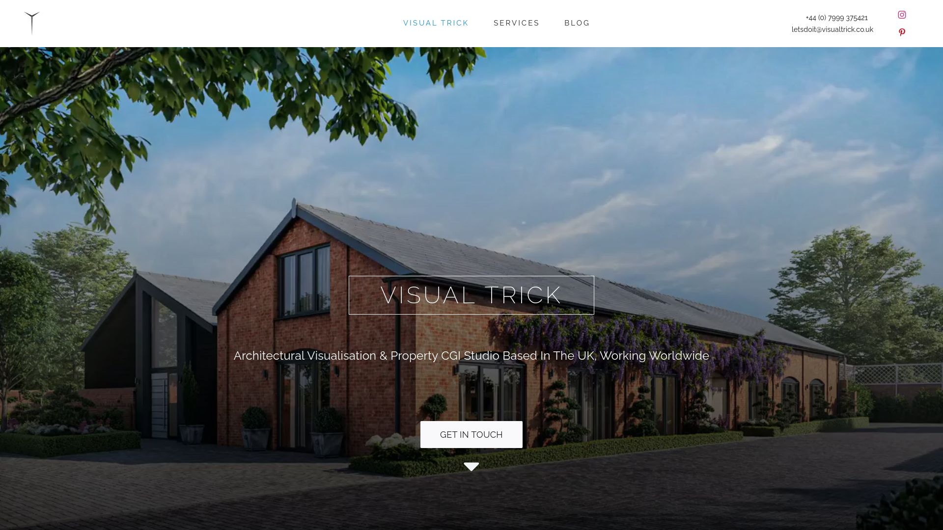
For a straightforward brief, agree your viewpoint schedule and AVR levels with the local planning authority first, then send us the viewpoint list and any survey data you already hold before production starts.
- We work from OS grid references, total station or LiDAR control points and retained EXIF metadata to build verified views that match the AVR level you specify.
- Methodology statements, control-point tables and alignment screenshots are delivered alongside the imagery, ready to attach to a planning submission.
- Direct communication with one operator throughout can mean fewer handoffs and more predictable delivery against a validation deadline.
Visit our planning visuals and verified views page to discuss a viewpoint schedule and request a quote.
Sources
- Appendix 1 – Accurate Visual Representations (Part 15) — Spelthorne
- Verified view methodology — St Albans (Appendix 7.5)
- London View Management Framework (LVMF) March 2012 — part 1
FAQ
What do AVR0, AVR1, AVR2 and AVR3 actually mean?
AVR0 to AVR3 is a cumulative scale for verified views used in UK planning. AVR0 shows location and size, AVR1 adds the degree of visibility, AVR2 adds architectural form and AVR3 adds materials and photorealistic rendering, with each level building on the one below it, as set out in the AVR classification guidance.
Which AVR level does a planning application actually need?
There is no single required level for every application: the correct AVR level depends on the sensitivity, prominence and statutory context of each viewpoint, agreed with the local planning authority. A distant or illustrative view may only need AVR0 or AVR1, while a sensitive townscape view close to a listed building usually needs AVR2 or AVR3.
How do I avoid delays when submitting verified photomontages?
Agree the viewpoint locations and the AVR level for each one with the local planning authority before commissioning the imagery, and submit a full methodology statement alongside the images. Local authority methodology examples, such as the verified view appendix from St Albans, show the level of survey and photographic detail that officers expect to see.
What deliverables should I ask for in a verified view brief?
Ask for the baseline photograph, a wireline or wireframe overlay, the rendered image where required, a control-point table with easting, northing and level, and a written methodology statement. Also specify the recommended print size and viewing distance so the panel is judged as it was intended to be seen.
Does Visual Trick produce AVR-verified photomontages for planning submissions?
Yes, Visual Trick produces CGI Photomontage and Verified Views for UK planning submissions, built around the survey data and AVR level agreed for each viewpoint. Details of the service are on the planning visuals page.
