
A planning-grade CGI workflow for a residential application follows this sequence: brief and objectives → verified site photography → context modelling using Ordnance Survey base data, LiDAR and 3D city meshes → BIM import and geometry clean-up → camera match and verified view production → render and post-processing → QC and verification statement → final deliverables. Get that sequence right and you hand the LPA exactly what it needs to validate and determine your application. Miss a step, and you risk a validation failure or, worse, a committee refusal based on a visual that raised more questions than it answered.
The essential deliverables for an LPA submission are:
- Photomontage or verified view (VVM) at each agreed camera position
- AVR level statement confirming the verification methodology
- CAD camera markers (.DWG or .DXF) showing surveyed positions on the site plan
- Datum, focal length and verified photo metadata notes
- Source data list covering OS licence reference, LiDAR provenance and any third-party city mesh attribution
Responsibility sits across three parties. The developer or project architect owns the brief and all approval sign-offs. A surveyor or specialist photographer handles verified site photography and control point capture. The visualisation studio owns context modelling, camera matching, rendering and the AVR verification statement.
Key takeaways
A planning-grade CGI workflow requires a surveyed camera position, a datum-matched context model, an AVR verification statement and a deliverable pack formatted to the LPA’s validation list requirements.
| Point | Details |
|---|---|
| Fix the workflow sequence | Brief → verified photography → context model → BIM import → camera match → render → QC → deliverables; never reorder these steps. |
| Insist on an AVR statement | Every submission should include a written AVR verification statement with camera co-ordinates, focal length, control points and software used. |
| Check the LPA validation list | Confirm the target authority’s specific requirements before finalising the deliverable list; expectations vary significantly between LPAs. |
| Use authoritative base data | Build context models on Ordnance Survey and LiDAR data and include licence attribution in the deliverables to support LPA cross-checking. |
| Commission Visualtrick | Visualtrick delivers the complete planning-grade workflow, from verified photomontage to AVR statements and web scenes, formatted for LPA submission. |
Table of Contents
- Why does planning-grade CGI change planning outcomes?
- What types of planning-grade visuals do you actually need?
- What do planning officers and LPAs actually expect from your visuals?
- Which data sources and software does a planning-grade context model need?
- What technical specs and file formats should your brief include?
- What is the step-by-step CGI workflow for a residential planning submission?
- How long does planning-grade CGI take, and what drives the cost?
- How do you brief a CGI studio for a planning submission?
- How does the workflow look in practice? A Visualtrick residential submission
- The common failures in planning visuals, and how to fix them
- Planning-grade CGI from Visualtrick: what to expect
- Sources
Why does planning-grade CGI change planning outcomes?
A planning officer reading a design-and-access statement works largely from drawings. A well-produced verified view does something drawings cannot: it places the proposed building into a photograph of the actual street, at the correct scale, from a position a pedestrian or neighbour would actually stand. That shift from abstract to concrete changes how officers, committee members and objectors read a scheme.
The stakes are highest in four situations:
- Complex urban context where massing relationships with adjacent buildings are contested
- Heritage settings where the impact on a listed building or conservation area is the determining issue
- Tall or edge-of-street schemes where daylight, overshadowing and street-scene proportions are under scrutiny
- Contentious massing where a vocal local objection campaign is likely to reach committee
Gov supports using accurate visual communication of proposals as part of good design practice, and it is increasingly reflected in how LPAs frame their validation requirements. Some authorities now publish explicit validation lists that call for CGI visualisations and verified views as named deliverables, not optional extras.
Pro Tip: Always display verified views with the camera position, focal length and AVR level clearly labelled on the image board. A view submitted without that data looks like a marketing render, not a planning document, and some officers will treat it as one.
The risk of misleading imagery is real and consequential. A view that flatters the scheme by using an unusually wide lens, an elevated camera position, or a palette that softens material contrast can draw a formal objection from a design review panel or a heritage body. Accuracy is not just a technical nicety; it is the difference between a visual that supports your case and one that undermines it.
What types of planning-grade visuals do you actually need?
The terminology in this field is used loosely, so it is worth being precise. Each visual type serves a different purpose in the planning application process, and choosing the wrong one for the wrong stage wastes budget and can leave gaps in your submission.
Photomontage is a composite image placing a CGI of the proposed building into a site photograph. It does not require a full verified camera methodology, but it must be accurate enough to be credible. Suitable for pre-application discussions and design development.
Verified view (VVM) is a photomontage produced using a surveyed camera position, a measured focal length and a datum-matched context model. The camera position is physically marked and recorded on site. This is the standard required by most LPAs for committee packs and formal submissions in sensitive contexts.
Accurate Visual Representation (AVR) is the broader term for any planning visual produced to a defined level of accuracy. AVR levels run from Level 1 (a wireframe or outline overlay confirming position and scale) through to Level 3 (a fully rendered, photorealistic composite). Most residential submissions require at least Level 2, which shows materials and massing without photorealistic lighting.
Aerial photomontage composites a CGI into an aerial or drone photograph, useful for masterplan schemes where the relationship between the proposed development and surrounding roofscape or open land is the key planning question.
Massing models and material studies are CGI renders without a photographic background, used during design development and pre-application to test options quickly. They are not submission-grade on their own but are valuable in a design-and-access statement.
Dusk and lighting views show the scheme after dark, relevant for applications where light spill, façade illumination or the visual character of an evening streetscene is a material consideration.
| Visual type | Best use stage | Typical LPA expectation |
|---|---|---|
| Photomontage | Pre-application, design development | Accuracy sufficient for officer discussion |
| Verified view (VVM) | Committee pack, formal submission | Surveyed camera, datum, focal length, AVR statement |
| AVR Level 1 | Validation, outline applications | Wireframe overlay confirming position and scale |
| AVR Level 2 | Standard residential submissions | Materials and massing shown, neutral palette |
| AVR Level 3 | Heritage, tall buildings, contentious schemes | Photorealistic composite, full verification |
| Aerial photomontage | Masterplan, large residential schemes | Drone or OS aerial base, surveyed match |
| Massing / material study | Design development, DAS | No photographic base required |
| Dusk / lighting view | Schemes with lighting conditions as material consideration | Paired with daytime verified view |
When to prefer a verified view over a stylised render: any time the application is going to committee, involves a heritage asset, or sits in a conservation area. Stylised renders are fine for marketing; they are a liability in a planning pack if they cannot be traced back to a surveyed camera position.
Interactive web scenes add genuine value for stakeholder engagement on larger schemes; using the Kudoflix Real Estate Video Maker can help produce engaging short videos or animated flythroughs to share with stakeholders effectively. Publishing a 3D web scene via ArcGIS Online lets consultees orbit the model, check sightlines and understand the proposal in a way a static board cannot replicate. For a contentious residential scheme with a public consultation requirement, that interactivity can reduce the volume of objections based on misunderstanding of scale.
You can see examples of planning-grade residential visuals, including verified views and photomontages, in Visualtrick’s residential CGI gallery.
What do planning officers and LPAs actually expect from your visuals?
The short answer: evidence, not just images. Some local planning authorities publish validation lists that set out specific expectations for CGI visualisations, and those lists call for camera metadata and provenance, not just attractive pictures.
The minimum accuracy evidence you need to supply:
- Surveyed camera position with National Grid co-ordinates (Easting, Northing, elevation above Ordnance Datum)
- Datum reference confirming the vertical datum used (Ordnance Datum Newlyn is standard)
- Focal length and sensor size of the camera used for the site photograph, confirmed against EXIF data
- Verified photo metadata including date, time and GPS confirmation where available
- CAD overlays or control points showing the camera position plotted on the site plan and section
AVR levels define how much verification is required. Level 1 is a positional check only. Level 2 adds material representation. Level 3 requires full photorealistic rendering with verified lighting conditions. In practice, verification means the studio can demonstrate that the CGI geometry aligns with the photographic background at the camera position recorded on site, using control points or a photogrammetric check.
LPA requirements vary. Before finalising your deliverable list, download the target authority’s local validation list and check it against your planned outputs. LPA discretion on submission formats is real: what satisfies one authority may not satisfy another, and a phone call to the case officer before submission is never wasted.
On licensing: if your context model uses Ordnance Survey base data or LiDAR from the Environment Agency, the source and licence reference must appear in the deliverables. OS data used in planning submissions typically falls under a Public Sector Mapping Agreement (PSMA) or a commercial licence. Your studio should confirm which licence covers the data used and include the attribution in the AVR statement.
QC steps before submission: check that the CGI geometry matches the approved drawings (not a superseded revision), verify that the camera position in the CAD file matches the surveyed position, confirm that the focal length used in the render matches the EXIF data from the site photograph, and have a second person review the AVR statement against the actual render before it leaves the studio.
Which data sources and software does a planning-grade context model need?
The quality of a verified view depends almost entirely on the quality of the context model. A model built on authoritative data is faster to validate, easier to cross-check and more credible in a contested application.
Authoritative data sources:
- Ordnance Survey base data (MasterMap Topography Layer, building heights, OS Terrain 50/5) for accurate plan positions and ground levels
Software and tools:
- ArcGIS Pro for assembling the city context model, running viewshed and line-of-sight analyses and publishing web scenes to ArcGIS Online for stakeholder review
ArcGIS workflows support integrated mesh scene layers, BIM building scene layers and published web scenes, which means the same model used for the verified view can be published as an interactive stakeholder tool without rebuilding from scratch. That is a significant efficiency on larger schemes.
When to commission a measured survey or UAV photogrammetry: if the site is on a slope, if surrounding buildings have complex rooflines, or if the LiDAR data is more than a few years old and significant development has occurred nearby. Specify deliverables as a georeferenced point cloud (.LAS or .LAZ) and a mesh (.OBJ or .FBX) so the studio can integrate them directly.
Pro Tip: Ask your surveyor to capture control points on permanent features visible in the site photographs. Those control points become the photogrammetric anchors that let the studio verify camera position without a separate site visit.
What technical specs and file formats should your brief include?
A brief that specifies formats upfront prevents the most common late-stage problem: a studio delivering files the LPA’s portal cannot accept or a printer cannot reproduce at board size.
| Deliverable | Format | Specification |
|---|---|---|
| Print photomontage boards | TIFF or PDF | 300 DPI minimum, A1 or A3 print size |
| Committee pack images | JPEG or PDF | 150 DPI minimum, A3, sRGB colour profile |
| Web / consultation images | JPEG or PNG | 72–96 DPI, 2400px longest edge, sRGB |
| Raw render passes | EXR or PSD | Full resolution, layered, for post-production |
| CAD camera positions | DWG or DXF | AutoCAD 2018 or earlier for compatibility |
| Scene export | FBX or glTF | For web scene or VR delivery |
| BIM exchange | IFC 2×3 or IFC 4 | Confirmed with the studio before export |
| Metadata report | Camera, focal length, datum, control points, software used |
The AVR verification statement should be a standalone PDF containing: the measured camera co-ordinates (Easting, Northing, elevation to Ordnance Datum), the control point list with residuals, the software used for camera matching and rendering, the focal length and sensor size, and a sign-off checklist confirming that the render has been checked against the approved drawings.
Pro Tip: Adopt a consistent file-naming convention from day one: [ProjectRef][ViewpointID][AVRLevel][Revision][Date]. An LPA case officer tracing a source file six months after submission will thank you, and so will your QA process during the project.
For exterior CGI deliverables, always supply both a print-resolution TIFF and a web-optimised JPEG. The TIFF goes into the planning portal submission; the JPEG goes into the public consultation documents and the committee report.
What is the step-by-step CGI workflow for a residential planning submission?
The workflow below applies to a standard residential scheme requiring verified views for a formal application. Adjust the depth of each step for the scheme’s complexity.
-
Brief and objectives (Week 1). Agree the camera viewpoint list, target deliverables, AVR level required, LPA validation list reference and the approved drawing set to model from. Confirm data licensing requirements. Sign off before any survey work is commissioned.
-
Site reconnaissance and verified photography (Week 1–2). A photographer or surveyor visits the site, photographs each agreed viewpoint using a calibrated camera, records GPS co-ordinates and captures control points on permanent features. EXIF data is preserved and supplied to the studio.
-
Survey and context model assembly (Week 2–3). The studio assembles the context model using OS MasterMap, LiDAR and any local 3D city mesh. Survey control is imported and the model is checked against OS Terrain data for datum alignment.
-
BIM import and geometry clean-up (Week 3–4). The Revit or IFC model is imported, checked against the approved drawings and cleaned for render. Any geometry errors or level discrepancies are flagged to the architect before proceeding.
-
Camera match and verified view production (Week 4–5). The studio matches the render camera to the surveyed position using control points. The CGI is composited over the site photograph and checked for alignment at multiple control points.
-
Render and post-processing (Week 5–6). Final renders are produced at the specified resolution and colour profile. Post-processing is limited to colour grading and sky replacement where permitted; no alterations that would affect the apparent scale or massing of the proposal.
-
QC and verification statement (Week 6). A second reviewer checks the render against the approved drawings, the camera position against the CAD file, and the AVR statement against the actual outputs. Any discrepancies are corrected before the statement is signed off.
-
Final deliverables and handover (Week 6–7). All files are packaged to the agreed naming convention, the AVR statement is finalised, and the complete deliverable set is handed to the project architect or planning consultant for submission.
Decision gates: the viewpoint list must be signed off before photography. The approved drawing set must be confirmed before BIM import. The AVR statement must be reviewed before final render. Each gate prevents rework that compresses the submission timeline.
Residential construction management best practice, as described in Procore’s construction management guide, emphasises disciplined preconstruction planning and defined phase gates to avoid schedule risk. The same logic applies here: a CGI workflow without sign-off gates is a workflow that will be restarted at least once.
How long does planning-grade CGI take, and what drives the cost?
Householder and small schemes (single dwelling, extension, small conversion): 2–4 weeks from receipt of confirmed drawings and site photography. One or two viewpoints, limited context modelling, straightforward camera match.
Medium residential schemes (5–50 units, infill or brownfield): 4–8 weeks. Multiple viewpoints, a more detailed context model, BIM import from a Revit model, and typically two rounds of client review before the AVR statement is finalised.
Large or complex schemes (50+ units, tall buildings, heritage settings, masterplans): 8 weeks or more. Full city mesh assembly, multiple AVR levels across different viewpoints, aerial photomontage, web scene production and a formal verification sign-off process.
The primary cost drivers are:
- Site survey requirements: a full measured survey or UAV photogrammetry adds cost but is sometimes unavoidable on complex sites
- Verified photography: a specialist photographer capturing control points costs more than a standard site visit
- Modelling detail: a scheme in a dense urban context with complex surrounding buildings takes longer to model than a suburban infill
- Number of viewpoints: each additional verified view adds survey, modelling and verification time
- Revision rounds: revisions after the camera match is set are expensive; revisions to the brief before photography are cheap
- AVR verification work: Level 3 verification with a formal sign-off process adds time and cost compared to Level 2
To reduce cost without compromising accuracy: fix the camera list before commissioning photography, bundle all images into a single project rather than commissioning piecemeal, and avoid requesting stylised marketing renders alongside planning-grade views until after permission is granted.
How do you brief a CGI studio for a planning submission?
A clear brief prevents the two most common problems: a studio that delivers beautiful images without the verification evidence the LPA requires, and a project that runs over budget because the scope was never fixed.
Checklist items to attach to a tender or purchase order:
- Approved plans, sections and elevations (confirmed revision)
- Site levels and Ordnance Datum reference
- Agreed viewpoint list with approximate camera positions marked on a site plan
- Target deliverables and file formats (reference the technical spec table above)
- LPA validation list reference or a note confirming no specific list exists
- Licensing notes for any third-party data the studio will need to source
- Submission deadline and any committee date that creates a hard deadline
Questions to ask a studio before commissioning:
- Can you provide examples of verified views submitted to and accepted by an LPA?
- How do you capture and verify camera positions — do you use a surveyor, GPS, or photogrammetric control points?
- What is your source data provenance for the context model, and how do you attribute OS and LiDAR data in the deliverables?
- What does your AVR verification statement contain, and who signs it off?
- How many revision rounds are included, and what triggers an additional charge?
- Who owns the CGI files and scene data on completion, and what are the licensing terms for reuse in marketing?
- Do you have experience with the specific LPA this application is going to?
A property architect visualisation checklist can help structure the brief before you approach studios.
On payment and revision rounds: structure payment in three stages — on brief confirmation, on completion of the camera match and client review, and on final delivery. Limit revision rounds to two after the camera match is set. Any revision that requires re-surveying a camera position should be treated as a scope change and priced separately.
How does the workflow look in practice? A Visualtrick residential submission
A useful way to see the workflow applied end-to-end is a residential infill scheme: a developer seeking permission for six dwellings on a backland site in a conservation area, with a heritage officer likely to scrutinise the roofscape impact from a public footpath.
Brief and inputs: The project architect supplied a confirmed Revit model (IFC export), approved drawings at RIBA Stage 4, and a viewpoint list of three positions agreed with the planning consultant. The LPA’s validation list required verified views at AVR Level 2 for the two street-facing positions and an aerial photomontage for the masterplan context.
Studio workflow: Visualtrick assembled the context model using OS MasterMap Topography Layer and 0.5m LiDAR from the Environment Agency. A specialist photographer visited the site, photographed all three positions with a calibrated camera, recorded GPS co-ordinates and captured four control points on permanent features visible in each photograph. The Revit model was imported, checked against the approved drawings and cleaned for render. Camera matching used the surveyed control points to verify alignment at each position. The aerial photomontage used an OS aerial base image matched to the context model.
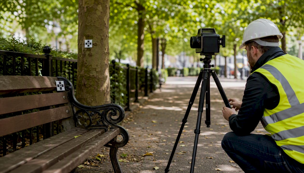
Timeline and review: The full workflow ran to six weeks from receipt of confirmed drawings. One round of client review after the camera match identified a minor discrepancy in the ridge height of one unit, which was corrected in the Revit model before final render. The planning consultant reviewed the AVR statement before sign-off.
Final deliverables: Three verified view boards (A1 TIFF, 300 DPI), one aerial photomontage board, an AVR verification statement PDF, CAD camera position files (.DWG), a metadata report and an ArcGIS web scene published to ArcGIS Online for the public consultation.
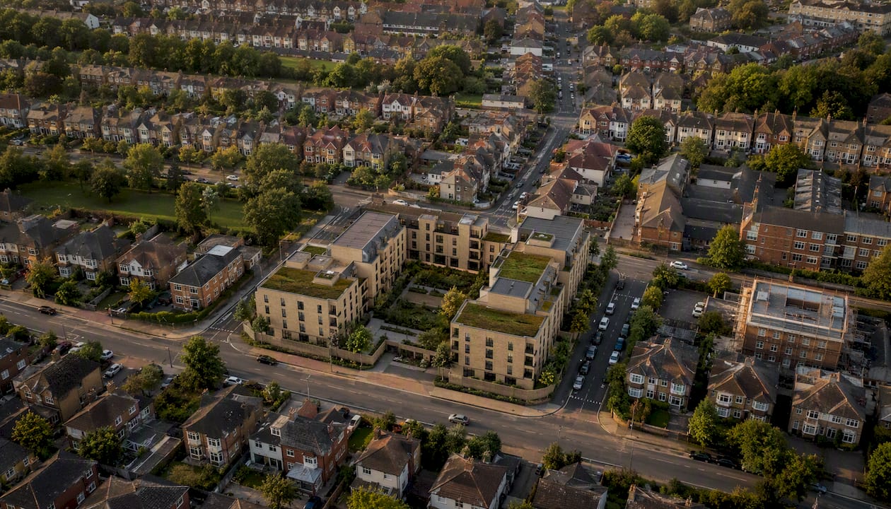
For a project team wanting to reproduce this quickly, the inputs required are: a confirmed IFC or Revit model, approved drawings, a signed-off viewpoint list, the LPA validation list reference, and a confirmed submission deadline. Everything else the studio can source and manage.
The common failures in planning visuals, and how to fix them
Most planning CGI problems are not technical failures. They are process failures that happen before the studio opens a single file.
The most damaging is missing camera data. A photomontage submitted without a surveyed camera position and focal length cannot be verified. An LPA that asks for verification evidence and receives none will either invalidate the submission or, if it proceeds to committee, give objectors an easy target. The fix is simple: make a written AVR statement a contractual deliverable, not an optional extra.
Over-stylised views are the second most common problem. A render with dramatic sunset lighting, lush planting at full maturity and a sky that belongs in a lifestyle brochure may look impressive in a marketing pack. In a committee report, it reads as an attempt to obscure the scheme’s actual impact. Planning officers are experienced readers of CGI; they notice when a view is designed to flatter rather than inform. For committee packs, use a neutral sky, mid-season planting and a colour palette that matches the actual proposed materials. Reserve the atmospheric renders for the marketing campaign after permission is granted.
Poor datum alignment produces a CGI that floats above or sinks into the surrounding ground plane. It is usually caused by a mismatch between the vertical datum used in the Revit model and the Ordnance Datum used in the context model. The fix is to confirm datum alignment at the BIM import stage, before camera matching begins.
Inconsistent lighting across views is a subtler problem. If one view shows the building in morning light and another in afternoon light, a design review panel will notice that the scheme looks different in each image and question whether the views are comparable. Use a consistent solar angle across all views in a submission pack, or state the solar angle explicitly on each board.
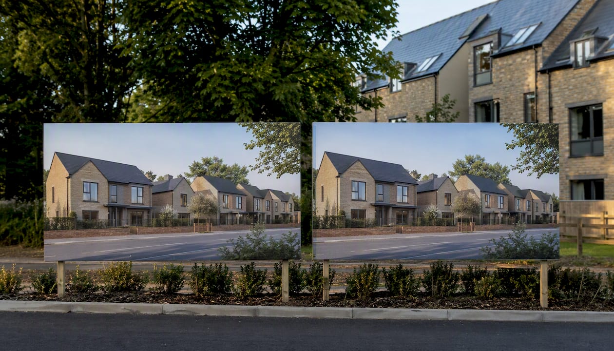
On integrating officer feedback into revisions: when a planning officer requests a change to a view, establish whether the request requires a new camera position (which means re-survey and re-verification) or a change to the CGI geometry or materials (which does not). The former is a scope change; the latter is a revision. Clarifying this distinction at the pre-application stage, or in the initial brief, prevents a disagreement mid-process.
Architectural CGI services that include a formal QC step and a written AVR statement are the most reliable way to avoid these failures reaching the LPA.
Planning-grade CGI from Visualtrick: what to expect
Visualtrick produces planning-grade CGI for residential applications across the full range of scheme types, from householder extensions to multi-unit urban infill. The service covers the complete workflow described in this guide: verified photomontage, AVR statements, context modelling from OS and LiDAR data, BIM integration from Revit or IFC, aerial photomontages, web scenes for public consultation and full deliverable packs formatted for LPA submission.
What clients receive is a submission-ready package: verified view boards at print resolution, an AVR verification statement, CAD camera files, a metadata report and, where required, an ArcGIS web scene. Typical timescales run from two weeks for a householder scheme to eight weeks for a complex residential development. Every project includes a formal QC step and a second-reviewer sign-off on the AVR statement before delivery.
To commission planning-grade visuals or to have your brief reviewed against the LPA’s validation list, contact Visualtrick directly via the CGI for planning applications service page.
Sources
The following sources are directly useful for confirming LPA expectations, technical workflows and data licensing requirements:
- Design
- CGI Visualisations
- Visualize construction planning in 3D
- Ordnance Survey
- 3D Visualization
- The Ultimate Guide to Residential Construction Management | Procore
