
A planning-grade photomontage starts with a full-frame sensor and a 24mm lens (roughly 74° horizontal field of view), a levelled tripod on a marked ground point, RAW capture through to a layered PSD or PSB deliverable, and a written Technical Methodology for anything claiming verified status. The Landscape Institute’s TGN 06/19 remains the reference framework that UK authorities expect consultants to follow.
TL;DR:
- A planning photomontage must be captured with a full-frame sensor and a fixed, level tripod, recording precise location, height, and camera settings for verifiability.
- Using a 24mm lens provides about 74° HFoV, balancing context and detail, with focal length and HFoV clearly documented alongside camera make and model.
- Deliverables should include RAW files, layered PSD or PSB files, embedded ICC profiles, and metadata, with resolution tailored to final print size, typically 180 to 300 ppi.
- Type 3 or Type 4 visualisations require a comprehensive Technical Methodology, including camera data, capture logs, and verification details supporting reproducibility.
- Reserve the highest verification standards for sensitive or contested sites, while most projects can adhere to proportionate Type 3 guidelines based on scale and context.
Table of Contents
- Camera, lens and framing specifications
- Capture process and on-site recording
- File formats, working files and colour management
- Presentation, scaling and technical methodology for planning submissions
- Verification, accuracy and a practical approach to planning-grade photomontage
- A one-page photomontage delivery checklist
- Practical perspective: choosing specs by project type
- How Visual Trick delivers verified photomontage and planning visuals
- Sources
- FAQ
Camera, lens and framing specifications
Sensor format sets the baseline for every other decision. A full-frame sensor is typically chosen for planning photomontage to align focal length and horizontal field of view (HFoV) with those commonly used by local authorities and landscape consultants. Working from a cropped sensor is possible, but the focal length must be converted to its full-frame equivalent before it appears in any methodology document, otherwise the HFoV claim will not match what a verifying officer expects to see.
Focal length choice depends on what the proposal needs to communicate. A 24mm lens typically gives about 74° HFoV and is commonly chosen in urban verified views as it balances capturing the proposal and sufficient surrounding context to judge scale, as documented in Spelthorne’s verified view methodology. A 35mm lens generally provides around 68° HFoV and may be used where context is more limited or less critical. A 50mm lens offers a narrower HFoV around 40°, suitable for isolated buildings or close-range detail shots when wide context is less important.

Tilt/shift lenses control converging verticals without the perspective distortion that a wide-angle lens introduces near the frame edges, and a single-shot capture is preferable to a stitched panorama wherever the required HFoV allows it, since stitching multiplies opportunities for parallax error.
Every delivery should record:
- Lens make and model, not just a focal length figure.
- The actual focal length used, converted to full-frame equivalent where relevant.
- The stated HFoV, expressed in degrees.
- Whether the shot was single-frame or stitched, and how many frames.
Capture process and on-site recording
Accuracy on site is what makes a photomontage defensible later. The camera position has to be fixed, recorded and repeatable, because any consultee or inspector may ask for a return visit to the same spot.
- Mark the tripod ground point clearly and record the location coordinates as precisely as possible.
- Set the camera height, typically around 1.60 metres, and note any deviation from that figure and why.
- Level the camera using a bubble level or an in-camera electronic level before every exposure.
- Capture images in RAW format, use exposure bracketing if lighting varies, and record weather and lighting conditions during capture.
- Document the tripod setup photographically as evidence of the viewpoint, and preserve unedited RAW files with associated metadata.
Pro Tip: Capture a short HDR bracket of any reflective surface in frame (glass, water, wet paving) so the compositor has real reference values for reflections rather than guessing at index of refraction later.
File formats, working files and colour management
The working file matters as much as the final export. Deliverables are best provided as layered PSD or PSB files retaining masks and adjustment layers for potential later editing or verification, since a flattened export cannot be corrected or re-verified if a planning officer queries an element later. Adobe’s own technical documentation confirms that PSD file format supports documents up to high pixel dimensions, with PSB format accommodating very large images beyond typical PSD limits, which is the format to specify once a document exceeds standard PSD limits.
- Use 16-bit color depth for heavy compositing to minimize tonal banding during adjustments.
- Embed an ICC color profile in all deliverable files to ensure consistent color management.
- Monitor calibration using dedicated hardware devices is recommended prior to color-critical work.
- Pixel dimensions should be chosen relative to the intended print size and desired resolution rather than using default export settings.
- Preserve and include image metadata such as EXIF, sidecar files, HDR logs, and reflection references alongside final images.
Professional imaging guidance recommends print resolution in the region of 180 to 300 ppi depending on output, which means an A1 sheet needs a substantially larger source file than an A4 proof, and that sizing decision has to be made before capture, not fixed in post-production.
Presentation, scaling and technical methodology for planning submissions
The baseline photograph and the final photomontage should be printed at the same size, with any enlargement factor clearly indicated. TGN 06/19 recommends enlargement figures of around 100% or 150% depending on the viewpoint distance and sheet size, and every submission should carry a “Visualisation Type: X” label so the reviewer knows immediately which level of rigour applies.
A3 sheets are generally appropriate for Type 3 visualisations, while A1 size is preferred for panoramas or views requiring wide context coverage. Alongside the images themselves, a submission pack should include:
- A viewpoint location plan showing the marked ground point and camera orientation.
- Survey references tying the viewpoint to the OS grid.
- Wireframe or mesh overlays demonstrating the model’s alignment against the photograph.
- A written Technical Methodology describing the capture equipment, compositing steps and verification checks used.
| Visualisation type | Typical use | Documentation required |
|---|---|---|
| Type 1/2 | Illustrative, early-stage or marketing context | Photograph, basic model overlay |
| Type 3 | Accurate visual representation for most planning applications | Camera data, HFoV, enlargement statement |
| Type 4 | Verifiable, high-sensitivity or contested sites | Full Technical Methodology, survey references, wireframe overlays |
Type 4 visualisations are typically required for sensitive sites or contested proposals where reproducibility and verification by inspectors is essential.
Verification, accuracy and a practical approach to planning-grade photomontage
CGI photomontage, aerial CGI photomontage, verified views and supporting verification reports can be produced for planning submissions. Supplying an index of refraction reference around 1.45 alongside HDR logs for reflective surfaces gives compositors real values to match rather than estimates, which matters when glazing or water features sit inside the frame.

These artefacts feed directly into a Technical Methodology: the viewpoint photograph, the wireframe overlay, the capture log and the reflection reference all become appendices that let a planning officer trace how the finished image was built. A photomontage verification report structured this way gives a consultee something concrete to check rather than a finished image they have to take on trust.
A one-page photomontage delivery checklist
Copy this into a brief or tender:
- Viewpoint OS grid reference and marked ground point photograph.
- Camera make, model and sensor format.
- Lens focal length and stated HFoV.
- Camera height and level confirmation.
- RAW files plus layered PSD/PSB working file.
- Embedded ICC profile and stated print resolution.
- Enlargement factor and Visualisation Type label.
- Written Technical Methodology for Type 3 and Type 4 outputs.
Marketing imagery can drop the last two items; Type 3 and Type 4 planning visuals cannot.
Practical perspective: choosing specs by project type
Reserve full Type 4 rigour for tall buildings, heritage settings or contested sites. Most other applications are proportionate at Type 3, where sensitivity and scale should guide HFoV and enlargement choices rather than a fixed template.
— Paride
How Visual Trick delivers verified photomontage and planning visuals
Commissioning a CGI photomontage or aerial CGI photomontage means handing over a brief once and getting a planning-ready pack back, rather than chasing revisions across several suppliers. Images are produced in-house, which helps keep deadlines predictable when a submission date is fixed and there is no room for a subcontractor to slip.
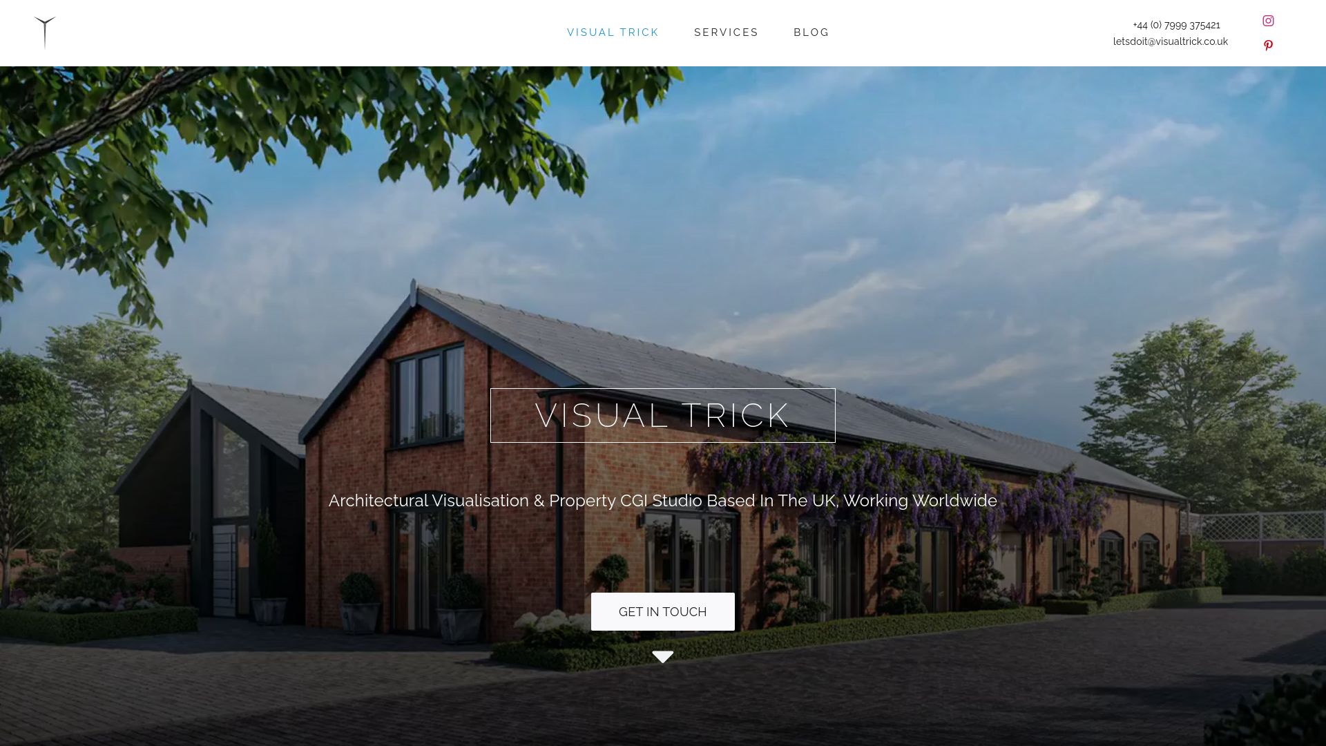
Our planning visuals service covers:
- CGI photomontage and aerial CGI photomontage for standard and elevated viewpoints.
- Verified views built to Type 3 or Type 4 documentation standards.
- Supporting verification reports and Technical Methodology appendices.
Get in touch to request a sample delivery spec or a verification report structured around your next site, and see how a single point of contact can carry a submission from viewpoint survey to finished pack.
Sources
For full technical appendices, consult TGN 06/19, the Spelthorne verified view methodology, Adobe’s PSD/PSB documentation, the ASMP digital photo guide and the academic photomontage compositing framework.
- Adobe Photoshop technical requirements and file format guidance
- LI TGN 06/19 visual representation (local authority copy)
- Spelthorne verified view methodology (Appendix)
- ASMP digital photo guide (colour management and resolution guidance)
FAQ
What are three defining characteristics of photomontage?
A photomontage combines two or more photographic elements into a single new image, arranges them through deliberate composition rather than accident, and produces a result that never existed as one original photograph. Contemporary planning photomontage practice typically layers a site photograph with an aligned render of a proposed building.
Can you give me an example of a photomontage?
A common example is a planning application image showing a proposed extension inserted into a photograph of the existing street, aligned to match the original camera position, lens and perspective. The finished image lets a reviewer judge scale and massing against the real context rather than an isolated render.
What resolution should a planning photomontage be?
Resolution should be set against the final print size rather than a fixed pixel count, with professional guidance pointing to 180 to 300 ppi depending on output. An A1 sheet therefore needs a substantially larger source file than an A3 proof at the same visual quality.
Do I need a Technical Methodology for every photomontage?
Only Type 3 and Type 4 visualisations under TGN 06/19 require a written Technical Methodology. Illustrative or marketing imagery does not need one, though recording capture details is still good practice.
What does Visual Trick include in a verified view?
Verified views typically include a CGI photomontage or aerial CGI photomontage aligned to the survey viewpoint, supported by verification reports and Technical Methodology appendices where the project requires Type 3 or Type 4 documentation. Reflection references and HDR logs may be supplied where glazing or water features appear in frame.
